
Concrete Spillway Condition Assessment with GPR

Embarkment dams and concrete dams are acting as a first line of defense to prevent thousands of residential homes and business offices from dangerous flooding. It’s not only the water that is posing a danger to the neighborhoods, but the aftermath of what the flood could leave behind. The insurance value of the affected property could go up, not to mention the rehabilitation/construction cost to fix water damage.
The first and most noticeable issue that flooding could cause is water damage on the affected properties, buildings and structures. The damage could vary, everything from low to severe damage. After a thorough visual inspection, construction could start to fix the water damage.
But what if the affected area is underground, beneath our concrete or asphalt pavement, therefore it is unforeseen, until the damage grows into a real hazard? Water finds its way thru porous materials. If this flowing water has significant speed, then chances are that the ground or soil could be washed out, whether it is compacted or non-compacted soil. If so, “large size” VOIDS or SINKHOLES could form below the surface. That defect would now have become a real HAZARD. This type of hazard is called UNKNOWN HAZARD and must be taken seriously. It is highly recommended to investigate every affected area that was flooded previously. This type of behavior would be an example of when to do a thorough risk assessment.
Ground Penetrating Radar is a suitable application to perform this type of condition assessment on concrete spillways or damns. It is a fast and reliable NDE (Non-Destructive Engineering) method that could provide valuable information on a large scale for further use of construction, design and engineering purposes. The collected data is combined with RTK corrected data that would provide us accurate coordinates of the detected anomalies. The whole project can be transformed into AutoCAD 2D/3D or any other AutoDesk platform so the end user would not have any issue receiving the results.
In the following images we will see the general procedure of a concrete spillway condition assessment. The image below indicates the actual survey site and the designated area of interest (see yellow dash line).

Setting up the 3D grid for the scan by establishing the common origin of GPR grids
Performing 3D GPR scan (1-4’ scan line increment in Lat/Long direction)
Data Interpolation, digital model
Data assessment, possible void location mapping
Vector and raster data export
Creating a digital contour map that indicates layer thickness and void map
Incorporate Digital Satellite Model with GPR images
GIS Interpretation
Every radar cross section is being analyzed for suspicious anomalies are marked accordingly on the plan view and cross section to create a georeferenced polygon.
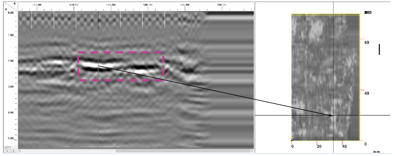
The result is presented in a 3D image that indicates the actual location and lateral size of possible voids (see radar images below).

Plan view Radar image filtered out map


Incorporated vector data with DTM (Digital Terrain Model) is indicating the location of possible voids underneath the concrete pad of the spillway.
NOTE: Coring or drilling for pilot hole is recommended to verify vertical size of detected voids.
As per the results, GPR method was able to detect different size of possible voids in the near depth. The investigation process was fast and reliable to detect potential hazards underneath the concrete spillway in a safe way.