What is GPR Radar?
How it works
Ground-penetrating radar (GPR) uses a high-frequency (e.g. 40 to 1,500 MHz – microwave range) EM pulse transmitted from a radar antenna to probe the earth. The transmitted radar pulses are reflected from various interfaces within the ground, and this return is detected by the radar receiver. Reflecting interfaces may be soil horizons, the groundwater surface, moisture saturation, rock/boulder/soil interfaces, ground defect, manmade objects (embedded steel reinforcement in a concrete structure) or any other interface producing a noticeable contrast in dielectric properties (density, moisture content, etc..). The dielectric properties of materials correlate with many of the mechanical and geologic parameters of materials. The emitted radar signal beam is introduced to the ground by an antenna that is in close proximity to the ground (ground coupled method). The reflected signals can be detected by the transmitting (Tx) antenna or by a second, separate receiving antenna (Rx).
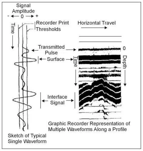
The received signals are processed and displayed in real-time on a graphic recorder. As the antenna (or antenna pair) is moved along the surface, the recorder system displays results in a 2D cross-section record or radargram of the earth. As GPR has short wavelengths in most earth materials (due to its high frequency domain), resolution is in direct proportional with the frequency. Higher frequency to be used provided high resolution but shallower penetration in earth materials or manmade objects. Therefore, the signal attenuation in earth materials is high, and depths of penetration seldom exceed 30ft in vertical. High conductivity materials such as type of Clays with a high cation exchange capacity increase the attenuation and decreasing penetration. In addition to that, the presence of solutes or other substances which increase the electrical conductance of groundwater and have the same attenuation and penetration results.
Figure 1 - Schematic illustration of common offset single-fold profiling.
Figure 2 - GPR received signal and graphic profile display. (Benson, Glaccum, and Noel, 1983)
The objective of GPR surveys is to map near-surface objects. For many as-built or concrete scanning surveys, the location of objects such as steel reinforcement, rebar, post-tension cable, electrical conduits in the concrete structure is the objective. Dielectric properties of materials are not measured directly. The method is most useful for detecting changes in the geometry of subsurface interfaces.
Subsurface problems conducive to solution by Mid Frequency 3D GPR methods are numerous and include the following: under pavement voids, sinkholes, pipes and tanks, location of the high moisture saturation in soil, locate groundwater surface, and others. However, as the results cannot be foreseen from the office, considerable latitude is given to the field geophysicist to incorporate changes in methods and techniques.
The physics of electromagnetic wave propagation are beyond the scope of this manual. However, there are two physical parameters of materials that are important in wave propagation at GPR frequencies. One property is conductivity (σ), the inverse of electrical resistivity (ρ). The relationships of earth material properties to conductivity, measured in mS/m (1/1,000 Ωm), are given in the section on electrical methods.
The other physical property of importance at GPR frequencies is the dielectric constant (ε), which is dimensionless. This property is related to how a material reacts to a steady-state electric field; that is, conditions where a potential difference exists but no charge is flowing. Such a condition exists between the plates of a charged capacitor. A vacuum has the lowest ε, and the performance of other materials is related to that of a vacuum. Materials made up of polar molecules, such as water, have a high ε. Physically, a great deal of the energy in an EM field is consumed in interaction with the molecules of water or other polarizable materials. Thus, waves propagating through such a material both go slower and are subject to more attenuation.
where
V= velocity in m/s,
ε = dielectric constant (dimensionless),
a= attenuation in decibels/m (db/m),
σ = electrical conductivity in mS/m.
Table 1. Electromagnetic properties of earth materials
Wightman, W. E., Jalinoos, F., Sirles, P., and Hanna, K. (2003). "Application of Geophysical Methods to Highway Related Problems." Federal Highway Administration, Central Federal Lands Highway Division, Lakewood, CO, Publication No. FHWA-IF-04-021, September 2003. http://www.cflhd.gov/resources/agm/
-

Structure Scan
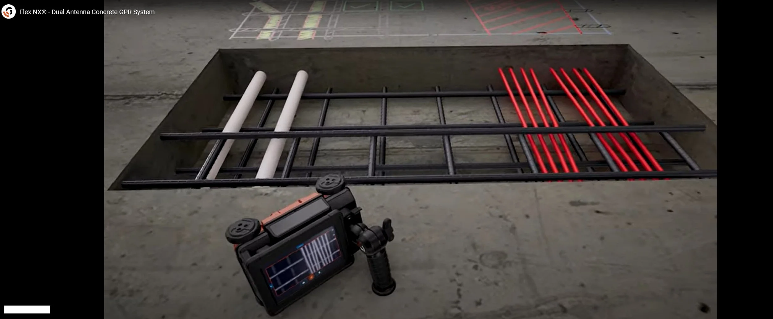
Concrete scanning with ground penetrating radar is a well-defined application. Unlike X-rays techniques, there are no issues with unsafe radiation. Concrete scanning with a high frequency antenna can locate many targets within concrete. For example, post tension cables, buried pipe or conduit, wires, reinforcing bars and voids. With optimal site conditions, one may be able to image a trench, drainpipe, waste pipe, or vent pipe beneath the concrete slab.
New concrete, precast concrete with void spaces, and concrete with metal fibers or metal screening often yield undesirable results. When looking concrete scanning services, know that we offer the best value and the best equipment and analytics.
-

Pavement Thickness Analysis
Working for DOT or an independent Engineering company this application would provide joint valuable information system for their data bank or project planning.
The method is similar to the other GPR techniques, except the antenna emits out signal from the air therefore this method is called Air Launched GPR. Data acquisition is fast, the surveying vehicle can move up to 60mph on a highways or roadways. The report is always presented in a common GIS form.
-

Subsurface Condition Assessments - Void Investigations
Subsurface condition assessment service is generally provided to the Oil and Gas Industry and Chemical Plants to provide them quality and safety assurance at the highest level. Working close together with area owners, plant engineers or Craning & Rigging department, a void survey is always recommended prior to heavy machinery placement or before any rigging, hoisting is taken place inside a facility. The provided map will be showing hot spots where ground quality is different, and the detected anomalies are showing some kind of abnormality in the soil underneath the area where a heavy crane will be erected or placed.
This information will be translated to the responsible party in order to take further action to mitigate the unknown danger(s).
Additional Services
Concrete scanning - BEAM
Concrete scanning on a PT slab
Layer thickness mapping
ST condition assessment
Subsurface investigations
Void and Sinkhole mapping
GIS data base
Road scanning
Industrial crane placement assurance
Ground Vibration Monitoring
Magnetic Susceptibility
Real Estate Assessments
Underground Storage Tanks UST
Private Utilities and Buried Metal Cables and Pipes
Environmental Landfills
As-built survey
Volumetric surveys
Environmental studies
Locating underground storage tanks
Concrete scanning
Archaeology
Engineering
Contamination
Real estate assessments
Drum Burials
Archaeology
Agricultural Geophysics Graves
Groundwater
Wind Farms (Ground Stability Assessments)
Sand and Gravel Exploration
Underground private cables and pipes
Facility locating
Concrete Scanning Xray
Electrical Power and Transmission Line Facilities
Engineering (non-environmental)
Environmental
Forensic Science
Geology


